DIY LED display board
 From our STAR Maker: Sohil Patel
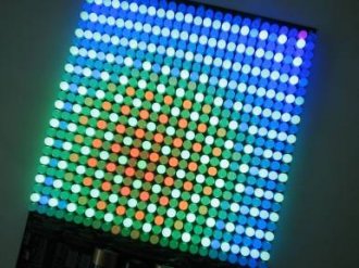
LED matrix the most preferred projects which are built using the Arduino. Its really fun using LEDs as well as the form of result you get from this is mesmerising. You should use these matrices for assorted applications such as for example generate cool sign boards with scrolling texts, to play animations, etc. Its actually inexpensive and easy to create one and certainly will be easily reprogrammed using the arduino. You can also customise it to be used in combination with the production of a music system, therefore we have cool synchronised visuals along with it.
Within guide i'll show you how to build a fancy 8 by 10 arduino LED matrix (with scrolling text and animations) utilizing the arduino and 4017 decade counter. You can also also purchase assembled LED matrix on the web. This particular matrix is easy to help make and plan and it's also a good way to learn about multiplexing.
Which are the stuff needed to do this?
1. 80 LEDs.
2. Eight 220Ohm resistors.
3. CD4017 decade counter IC.
4. Ten 1K resistors.
5. Ten 2N3904 transistors.
6. Single strand wire.
7. Solder dot board.
8. Arduino.
How can it work?
 This whole arduino LED matrix project works on the concept of multiplexing. Right here, the arduino is attached to the 4017 ten years countertop IC and delivers the information through two lines. The multiplexed data from arduino will be decoded into split indicators the LEDs via the 4017 IC. This after that drives the corresponding LEDs in different rows.
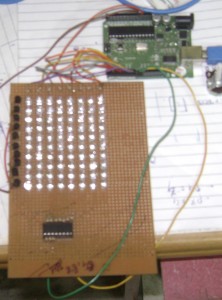
1 : Soldering the Matrix
Deciding on the best LEDs is one of the most important parts of this task, because deciding on the best ones is quite critical into execution for this project. I would suggest using 5mm diffused LEDs since they provide a decent amount of brightness and delivers a definite image.
Soldering the arduino LED matrix could be the tricky part, there is a large number of methods to get it done and I will share my method to you. You will need to connect most of the good leads for the LEDs in columns in addition to bad leads in rows. You can use the solder dot prototyping board for soldering the LEDs onto it. Drive the LEDs through the adjacent holes in the board. Make use of the circuit figure below to get in touch the arduino LED matrix together.
Then, use the good lead of first LED and flex it down to another LEDs, solder the pins which touch each other. Next, make the last lead that you soldered and flex it once more down and repeat till you have all the positive leads connected inside column. Snip from the additional length of the prospects that you performedn’t usage.
 today a brand new dilemma is created ;) which: linking the negative pins consecutively, because you can’t fold all of them and solder like you performed because of the good leads, because it will short each other. My strategy saves a lot of time and is less complicated. The key will be place some tape or simple adhesive tape on column’s connections to isolate them from the negative pins. If you do as you are able to bend the unfavorable prospects also and connect them like you did aided by the positive ones. Plus they will not quick both as they begin to be isolated :)
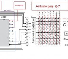
The circuit for the arduino LED matrix is as shown:
Through a resistor you must connect each line toward arduino (pins 0-7). The reset pin associated with 4017 goes to pin 8 regarding the arduino as well as the time clock pin would go to pin 9 on the arduino.
Step 2 : Multiplexing the Arduino LED matrix
Just what exactly is multiplexing:
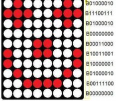
Its fundamentally an approach to separate information into small pieces and deliver it one-by-one. That way you can save a lot of pins regarding arduino and maintain your program fairly simple. Within our case we separated the picture we need display into 10 pieces (10 rows). We should scan the rows of the matrix (illuminate one line at the same time) and send resources from arduino towards the columns. All the articles tend to be positives of the LEDs plus the rows tend to be downsides. So if the very first line is connected to ground therefore we deliver sign on first line, it'll just light the very first LED within the line.
To have a beneficial show we must scan the rows quickly, so fast the the human eye believes that all of the rows tend to be linked at the same time.
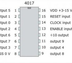
The Reason Why IC 4017:
The 4017 features 10 result pins, so we need 10 resistors and 10 transistors. We link the 1K resistors into outputs regarding the 4017 and its particular various other end towards base of the transistor as shown in the circuit figure at the top of this page. After that, we connect the collectors of the transistor towards the LED rows and also the emitter to the ground. You may also make use of BC547 npn transistor.
Step 3: Programming the arduino LED matrix
We have written somewhat system that scrolls text and included most of the letters and numbers to it also. I utilized ports for my program as it saves area and it is much easier to handle.

RELATED VIDEO


Share this Post
Related posts
How to build LED display Board?
ENHANCE!! Schematic is ON LINE! ENHANCE 2!! Code is ON LINE! This task details my quite fast build of a 24x8 matrix. My determination…
Read More
Led display board software
Huge E-Board for Corporate and Academic Companies This all-in-one E-Board screen solution provides portability and flexibility…
Read Morelatest posts
-
 LED Projector Lamp price January 16, 2024
 -
 LED light bulbs for sale cheap January 11, 2024
 -
 Light Bulb Shapes January 6, 2024
 -
 LED curing light for Gel nails January 1, 2024
 -
 LED Spot light bulbs December 27, 2023
 -
 Info on LED lights December 22, 2023
 -
 LED light Nail Dryer December 17, 2023
 -
 LED light for Gel polish December 12, 2023
 -
 LED Decorative Lamps December 7, 2023