7 segment LED display PDF
Today I opened my brand-new Sparkfun 7-Segment show and tried my hand at using it as a broad purpose Arduino controller. My ultimate program is to try using it to operate a vehicle a stepper engine and answer the input of a push key. However, this product interested myself given that it has 4 7-segment Light-emitting Diode shows mounted on it, which means my project could provide some minimum visual feedback.
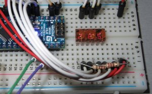
Very first, we launched the package and soldered 6 header pins on the end — place them inside in which the package is silk screened with a little white line. I plugged in a FTDI connector and plugged that into my Mac. It exhibited a zero on the firstly the LED shows.
Next we installed the Arduino IDE as well as the FTDI driver for my Mac. The directions for FTDI driver installer believed to run a command `sudo kextunload –b com.apple.driver.AppleUSBFTDI` but that simply provided me with a mistake message (“Can’t create –b. Can’t generate com.apple.driver.AppleUSBFTDI.”) so I don’t know if it did something.
Next I tried operating some sample SevSeg.cpp files but had difficulty.
We noticed I needed to plan this product using a meaning given by Sparkfun. I used the instructions in this repo’s readme file to put in those meanings: after which selected “Sparkfun Serial 7-Segment show” from the Arduino IDE Tools -> Board menu.
I discovered the SevSeg project and copied the data (SevSeg.cpp and SevSeg.h) next to my Arduino task file (SayHello.ino). Word of warning: This collection only gives off a blank character for letters that don’t have mapping into LCD (e.g. K, V, W, M…) i suppose it is cool so it also attempts to draw any letters anyway…
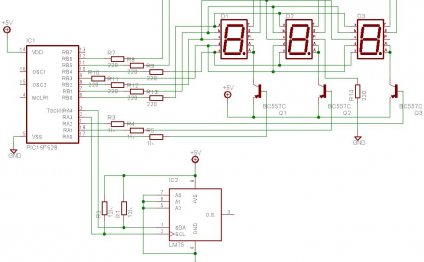
Finally I experienced to determine the pin purchase with this particular display. The SevSeg task needs about 18 integer variables if it is initialized… and I had trouble mapping pinouts (for example using this spec for the display: towards variables. One of the things I’m straight away finding myself frustrated within Arduino may be the lack of transparency around exactly what pins tend to be called…. obviously each board renames the ATMega pins (which have names like PB0 or PC4) to a new quantity. Finally I became in a position to solve this by looking at the firmware the Sevseg display and copying one of the keys values from there:
int digit1 = 16; // DIG1 = A2/16 (PC2)
int digit2 = 17; // DIG2 = A3/17 (PC3)
int digit3 = 3; // DIG3 = D3 (PD3)
int digit4 = 4; // DIG4 = D4 (PD4)
//Declare just what pins are connected to the portions
int segA = 8; // A = D8 (PB0)
int segB = 14; // B = A0 (PC0)
int segC = 6; // C = D6 (PD6), shares a pin with colon cathode
int segD = A1; // D = A1 (PC1)
int segE = 23; // E = PB7 (perhaps not a typical Arduino pin: Must include PB7 as digital pin 23 to pins_arduino.h)
int segF = 7; // F = D7 (PD6), stocks a pin with apostrophe cathode
int segG = 5; // G = D5 (PD5)
int segDP= 22; //DP = PB6 (perhaps not a standard Arduino pin: Must include PB6 as digital pin 22 to pins_arduino.h)
RELATED VIDEO
Share this Post
Related posts
7 segment LED display datasheet
Wiring a seven section screen may be a bit complicated, this guide is designed to be an useful guide to enable you to get…
Read More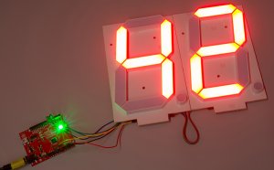
Large 7 segment LED display
Foam Board - just like most each of my Light-emitting Diode array projects, I like to use crafting foam board due to the…
Read Morelatest posts
-
 LED Projector Lamp price January 16, 2024
 -
 LED light bulbs for sale cheap January 11, 2024
 -
 Light Bulb Shapes January 6, 2024
 -
 LED curing light for Gel nails January 1, 2024
 -
 LED Spot light bulbs December 27, 2023
 -
 Info on LED lights December 22, 2023
 -
 LED light Nail Dryer December 17, 2023
 -
 LED light for Gel polish December 12, 2023
 -
 LED Decorative Lamps December 7, 2023