7 segment LED display datasheet
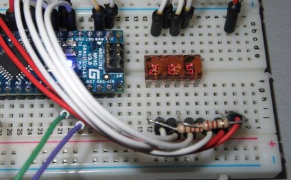
Wiring a seven section screen may be a bit complicated, this guide is designed to be an useful guide to enable you to get started. A seven segement display is basicly just a lot of LED's wired collectively in a single user friendly bundle. Some shows have actually a DP (dotted point) many do not, check out the datasheet to know what type you're getting.
Common Cathode versus Anode
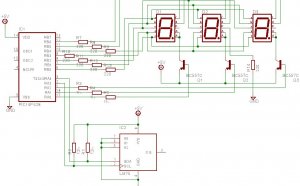
We start with identifying if our 7 part display component features a standard cathode (bad part) or anode (positive side). To determine this you search the part quantity online and check the datasheet. Within situation (a HDSP-5503) the component has a comon cathode. Generally in most datasheets this really is discussed into the text, in case it isn't you can easily determine this yourself by taking a look at the interior wiring schematic for the part (see picture below) where in fact the LED's tend to be shown due to their polarity, the way the schematic sign arrow is pointing to may be the cathode (unfavorable) side, one other side is the anode (good) part. We could in addition see into the datasheet that the common ground is found at Pin 3 and Pin 8. They're the actual only real 2 pins were all LED's are attached to.
Determining LED resistor price
Our seven segment display will require resistors at each knee to stop the LED's from drawing to much current. Our datasheet tells us each Light-emitting Diode has a maximum forward voltage of 20mA, therefore we make use of slightly less to save the LED somewhat, we're selecting 12.5mA. Utilizing Ohms Law we are able to quickly figure out the weight required.
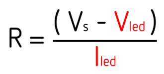
R = the resistance we should calculate
Vs = the origin voltage (our company is selecting 3.3V)
Vled = the current drop across our Light-emitting Diode (our datasheet tells us 1.8V)
Iled = the existing through the resistor (we're picking 12.5mA)
therefore in our situation the effect is 120Ω (Ohm)
We have to put a resistor at each and every pin of this value to stop the LED's from blowing up. Whenever we would only put 1 resistor on common pin as an example the LED's would get various amounts of current for each digit you are trying to show, in the event that you would only show similar digit each time you will get away by calculating the full total present resistor worth but because each LED inside our instance is separately addressable we need to put a resistor at each and every of them.
Generating your digits
To create your digits we just map the matching LEDs to a byte. Whenever we want the most effective LED club of our section to light we very first know which port quantity is affixed, lets state the utmost effective club is connected to the 4th pin our our change register we are able to compose this in byte as:, to make use of it with an arduino we could easily reference our digits using a dictionary similar to this:
byte one = 0b00010010; byte two = 0b01100111; byte three = 0b01110110; byte four = 0b11010010; byte five = 0b11110100; byte six = 0b11110101; byte seven = 0b00010110; byte eight = 0b11110111; byte nine = 0b11110110; byte zero = 0b10110111; byte test = 0b10000000; byte vacant = 0b00000000; byte figures = {zero, one, two, three, four, five, six, seven, eight, nine};
RELATED VIDEO

Share this Post
Related posts
7 segment LED display PDF
Today I opened my brand-new Sparkfun 7-Segment show and tried my hand at using it as a broad purpose Arduino controller…
Read More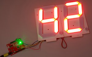
Large 7 segment LED display
Foam Board - just like most each of my Light-emitting Diode array projects, I like to use crafting foam board due to the…
Read Morelatest posts
-
 LED Projector Lamp price January 16, 2024
 -
 LED light bulbs for sale cheap January 11, 2024
 -
 Light Bulb Shapes January 6, 2024
 -
 LED curing light for Gel nails January 1, 2024
 -
 LED Spot light bulbs December 27, 2023
 -
 Info on LED lights December 22, 2023
 -
 LED light Nail Dryer December 17, 2023
 -
 LED light for Gel polish December 12, 2023
 -
 LED Decorative Lamps December 7, 2023