LED Bar Graph display
IC Analysis
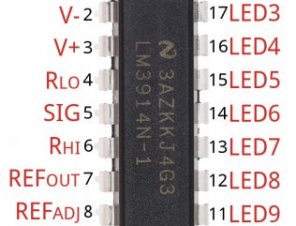
On this page we’ll see the pinout regarding the 18-pin LM3914/6. We’ll also dig some deeper to see what makes the ICs do whatever they do.
The Pinout
Over 50 % of the pins come in charge of driving the LEDs. The residual pins can be used for energy, guide voltages, and control over the IC. Here is an overview associated with chip’s pinout:
| Pin # | Pin Title | Pin Function | ||
|---|---|---|---|---|
| LED 1 | First (lowest worth) LED | 18 | LED 2 | 2nd LED |
| V− | Ground | 17 | LED 3 | third LED |
| V+ | Supply voltage (3-25V) | 16 | LED 4 | 4th LED |
| RLO | Divider low voltage | 15 | LED 5 | 5th LED |
| Signal In | Analog signal in | 14 | LED 6 | 6th LED |
| RHI | Divider high voltage | 13 | Light-emitting Diode 7 | 7th LED |
| Ref Out | Guide output voltage | 12 | LED 8 | 8th LED |
| Ref Adj | Voltage reference adjust | 11 | LED 9 | 9th LED |
| Mode | Dot/Bar mode choose | 10 | LED 10 | Last (higest analog input) LED |
That could seem a daunting a number of pins and guide voltages to provide, but in reality it can be very easy. A lot of pins can either be associated with ground, VCC, and/or left floating. Various other pins may require a resistor or two to set constant present or voltage values.
LED Outputs
The Light-emitting Diode outputs are typical open-collectors, so that they sink present. Link the cathode of a resulted in these pins and connect others pin associated with LED – the anode – towards voltage supply. There's no necessity for current-limiting resistors, as the processor chip takes care of existing legislation.
 Mode Select
The Mode pin enables you to select between “bar” mode and “dot” mode. In club mode, all LEDs sequentially start. Therefore, if signal current is near maximum, all LEDs is on. In “dot” mode just an individual LED is on anytime. Connect mode right to the energy resource for bar mode, and leave it floating for dot mode.
| Mode | Mode Pin Establishing |
|---|---|
| Bar Graph | Tied directly to V+ |
| Dot Display | Kept floating (no connection) |
| Dot Show (cascaded motorists) | Mode pin of first motorist linked to pin 1 of next. |
Setting the Analog number with RHI and RLO
The RHI (pin 6) and RLO (pin 4) pins are acclimatized to map the sensing number of the LM3914/6. RHI establishes the maximum voltage, and RLO sets the minimum voltage.
Those two pins is connected to any current as long as it is 1.5V underneath the offer current (V+), and greater than 0V.
Setting LED Existing with Ref Out
The current drawn out of Ref Out pin (pin 7) sets the existing that flows through each LED, which means this pin enables you to adjust the LED brightness.
If a resistor (RL) is connected from that pin to floor, the present streaming through each LED will undoubtedly be about add up to this equation:
So, for instance, if you have a 1kΩ resistor linked from pin 7 to ground, the Light-emitting Diode up-to-date should-be around 12.5 mA.
If you have a far more complex circuit attached to this pin, remember that the current between Ref Out and Ref Adj pin (pin 8) should always be 1.25V. Plus the LED up-to-date is equal to 10 times the current taken from Ref away.
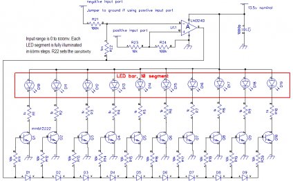
The Internals – A Chain of Comparators
Note: It’s not important to comprehend exactly how these potato chips work, however it is a neat study into the internals of an integral circuit. Feel free to skip into the, if this looks a touch too just like a Circuits we class.
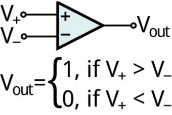
Each LED is managed by the output of a comparator, that will be a very simple op amp circuit. If voltage entering the + (non-inverting) pin is greater than that entering − (inverting), the comparator outputs a-1 (large, or, in cases like this the pin “floats”). If the − pin current is higher than +, the output associated with the comparator is a 0 (pulled towards surface).
The input/output combinations of a comparator.
Inside the processor chip, the analog control signal from pin 5 is connected to all the inverting (−) inputs on the comparators. The non-inverting (+) inputs associated with the comparators are attached to a string of 1kΩ resistors, which generate larger-and-larger voltage dividers. The + current from the very first comparator is the divider feedback voltage (RHI − RLO), as the + voltage in the final comparator is 1/10th of this voltage.
To show a Light-emitting Diode on – indicating the comparator’s production is 0 – the analog sign current should be greater than the divided feedback on a comparator. So a smaller sized signal voltage must start the initial LED in comparison to any of the after.
Voltage and Current Score
The LM3914/6 ICs have actually a very broad supply voltage range: anywhere from 1.8V to 18V.
The voltage amongst the RHI and RLO pins could be everything between 0V (believed, that couldn’t be also useful) and 1.5V underneath the offer voltage. Therefore, if you’re powering the chip at 5V, it’ll only be able to map voltages between 0V and 3.5V.
In addition, keep in mind current that might be streaming through the processor chip. Each LED can take between 7 and 13 mA, also to provide you with the chip you’ll require one more 2 to 9 mA.
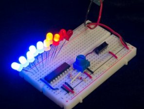
Example Hookup - Easy Dot/Bar Show
About this web page, we’ll look at an easy to use, single IC, 10 Light-emitting Diode hookup. This can show you how to set the Light-emitting Diode existing, the divider voltage, and exactly how to pick between dot or club screen mode.
This circuit is useful for both an LM3914 and LM3916. The only real huge difference would be the of analog voltages required to start all the LEDs.
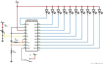
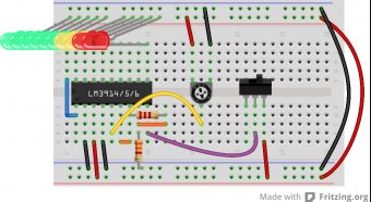
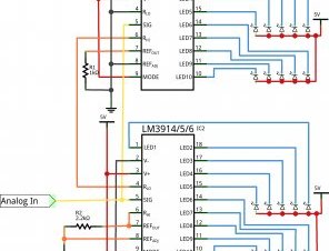
Breadboard and Schematic See
Listed below are a couple of diagrams that information this easy layout. We’ll believe the circuit is running on 5V. When your offer voltage differs from the others, some resistor values may prefer to alter (see further below).
Schematic view of simple LM3914 circuit.
Breadboard view of LM3914 circuit.
The analog input in this example is a potentiometer, which can be advantageous to testing, but boring otherwise. Please replace that for any analog sensor, if not an audio signal from a microphone or stereo.
The switch enables you to swap between dot or bar mode. If the mode pin is drawn high, the IC will undoubtedly be in club mode. If that pin is left drifting, the screen works in dot mode.
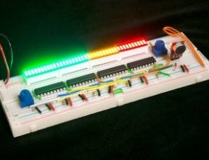
Finally, the LEDs. Pick any combination of color or size that you like. These 10-output LED drivers are perfect for the 10-Segment club Graph LEDs. You can also pick a mix of other LEDs it's likely you have handy. 5mm LEDs are a touch too huge to fit perfectly into this breadboard hookup, so you might need artistically bend them to ensure they are fit:
There's no necessity for current-limiting resistors, but ensure you have actually each LED connected in proper course (anode is linked to your power, cathode to IC pin).
There are a selection of solutions for running the display. Inside example above we utilized a 5V Wall Wart attached to a Barrel Jack Adapter, with a set of cables moving after that into breadboard. If you use a breadboard, the 5V/3.3V Breadboard Power Supply might create yourself better.
Establishing the Reference-voltage and LED Current
The 2 resistors in this circuit are widely used to set the up-to-date streaming through the LEDs, while the high voltage end regarding the current divider.
RELATED VIDEO
Share this Post
Related posts
Z-Bar LED Desk Lamp
Energy Saving Ships to Canada The Z-Bar Gen 3 LED table Lamp from Koncept Lighting features the award-winning three-bar design…
Read More
LED Architect Desk Lamp
Rated 5 out of 5�by Johnboy she actually is a success! Making use of as a piano lampnice varynice flexibilitysuper bright…
Read Morelatest posts
-
 LED Projector Lamp price January 16, 2024
 -
 LED light bulbs for sale cheap January 11, 2024
 -
 Light Bulb Shapes January 6, 2024
 -
 LED curing light for Gel nails January 1, 2024
 -
 LED Spot light bulbs December 27, 2023
 -
 Info on LED lights December 22, 2023
 -
 LED light Nail Dryer December 17, 2023
 -
 LED light for Gel polish December 12, 2023
 -
 LED Decorative Lamps December 7, 2023