LED matrix display project
From our CELEBRITY Maker : Vinayan Hari
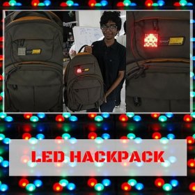
A simple project to produce cool 8bit art and cartoon on the backpack! This might be an instant and easy project you could end in minutes and show-off to your friends. Exactly what it can is, whenever you move your backpack, a dot matrix screen transforms on and shows any personality you have programmed inside. In cases like this its a fun pixelated personality.
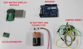
Which are the things expected to try this project?
2. Arduino
3. 9v Battery & Connector / virtually any lightweight power source.
4. ADX335 Accelerometer Module
5. Jumper wires
How does it work?
 The objective regarding the project should light a character on a dot matrix screen. The screen should illuminate whenever you move the bag. There are two main components for this project.
Part 1: The Wake Component
This part makes use of the accelerometer to feel once the bag techniques. The accelerometer delivers this information into the Arduino via the ‘Analog In’ pins.
Part2: The Show Part
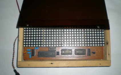
The screen shown on the LED matrix is driven because of the MAX7219 IC. It talks to the Arduino using the SPI protocol. But we don’t have to know a lot about any of it because there’s a library “ledcontrol” that does the job for us.
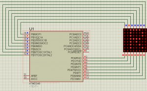
STEP 1 : Wiring up the Dot Matrix show, Arduino and Accelerometer
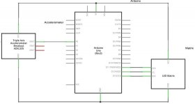 The circuit can be as self-explanatory whilst gets. The accelerometer returns analog values for acceleration in each axis. But here we only require the values for example axis. So connect either the X, Y or z-axis production through the accelerometer to your of this analog input pins (I have used A0 when you look at the rule offered). Switch on the accelerometer. Be careful at this time because some segments use 3.3V plus some use 5V. Give energy consequently or otherwise you may end up with a burnt component. Connect its surface (GND) into the ground on Arduino.
The dot matrix screen has 3 input pins DIN (Data in), CS (processor chip Select) and CLK (Clock). They are SPI (Serial Peripheral program) pins. Like I stated before, the library does the job for us :) They are all digital, connect them to any of GPIO pins. I linked DIN to pin 13, CS to pin 12, CLK to pin 11 into the rule supplied.
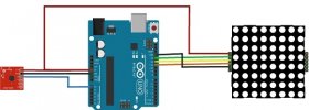 The dot matrix screen consumes energy through the 5V pins through the Arduino. Connect floor (GND) to your surface regarding the Arduino. And that’s all there is because of the circuit.
STEP TWO : The Code
We must include the LedControl.h library to our code. It’s this that makes conversing with the LED dot matrix screen exceedingly simple. Its available right here:


RELATED VIDEO

Share this Post
Related posts
8x8 LED matrix display
What exactly is better than an individual LED? countless LEDs! An enjoyable option to make a little display is to utilize…
Read More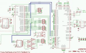
LED matrix display Driver
When you need some help operating most LEDs, the MAX7219 is the greatest friend you can expect. Most of us realize that if…
Read Morelatest posts
-
 LED Projector Lamp price January 16, 2024
 -
 LED light bulbs for sale cheap January 11, 2024
 -
 Light Bulb Shapes January 6, 2024
 -
 LED curing light for Gel nails January 1, 2024
 -
 LED Spot light bulbs December 27, 2023
 -
 Info on LED lights December 22, 2023
 -
 LED light Nail Dryer December 17, 2023
 -
 LED light for Gel polish December 12, 2023
 -
 LED Decorative Lamps December 7, 2023