RGB LED matrix display
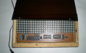
Bring a little bit of occasions Square into the house or apartment with this totally adorable 5 inches square 32 x 32 RGB LED matrix panel. These panels are typically regularly make video wall space, within ny we see them in the sides of busses and bus stops, to show animations or brief movies. We thought they looked awesome so we picked up a few cardboard boxes of these from a factory. They usually have 1024 brilliant RGB LEDs arranged in a 32x32 grid in the front with 4mm grid spacing. In the straight back there clearly was a PCB with two sets of double IDC connections (two input, two output: in theory you'll chain these collectively) and 12 16-bit latches that enable you to definitely drive the display with a 1:16 scan price.
These displays tend to be 'chainable' - connect one output to another input - but our Arduino example rule cannot help this (yet). It takes increased rate processor plus RAM compared to the Arduino features!
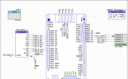
These panels need 13 digital pins (6 bit data, 7 little bit control) and an excellent 5V supply, to 4A per panel. We suggest our 4A regulated 5V adapter then linking a 2.1mm jack. Kindly check out our guide for more details!
Includes: an individual 32x32 RGB panel, two IDC cables, an electric cable, 4 mounting screws and mini-magnets (it appears they're usually installed on a magnetic base)
Keep in mind that these displays are designed to be driven by FPGAs or other high-speed processors: they do not have built in PWM control over all kinds. Rather, you are designed to redraw the display screen over and over to 'manually' PWM everything. On a 16 MHz arduino, we were able to press 12-bit shade (4096 colors) with 40per cent CPU consumption but this display would truly shine if driven by any FPGA, CPLD, Propeller, XMOS or any other high speed multi-core operator. Fortunately the display is pre-white balanced with good uniformity so if you start all the LEDs its maybe not a particularly tinted white.
Naturally, we'dn't leave you with a datasheet and a "best of luck!" We have a complete wiring diagrams and working Arduino library rule with examples from attracting pixels, outlines, rectangles, circles and text. You will get your color blasting inside the time! On an Arduino, you need 13 electronic pins, and about 1600 bytes of RAM to buffer the 12-bit shade picture. At the moment we would not have wiring documentation the MEGA.
Take note! These panels are remainder stock from factories that make huge light panels. That is why, the design and size might range from group to batch, even though the standard operation, codebase and tutorial is the same.
RELATED VIDEO
Share this Post
Related posts
LED matrix display project
From our CELEBRITY Maker : Vinayan Hari A simple project to produce cool 8bit art and cartoon on the backpack! This might…
Read More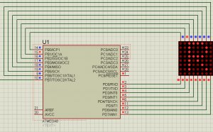
8x8 LED matrix display
What exactly is better than an individual LED? countless LEDs! An enjoyable option to make a little display is to utilize…
Read Morelatest posts
-
 LED Projector Lamp price January 16, 2024
 -
 LED light bulbs for sale cheap January 11, 2024
 -
 Light Bulb Shapes January 6, 2024
 -
 LED curing light for Gel nails January 1, 2024
 -
 LED Spot light bulbs December 27, 2023
 -
 Info on LED lights December 22, 2023
 -
 LED light Nail Dryer December 17, 2023
 -
 LED light for Gel polish December 12, 2023
 -
 LED Decorative Lamps December 7, 2023