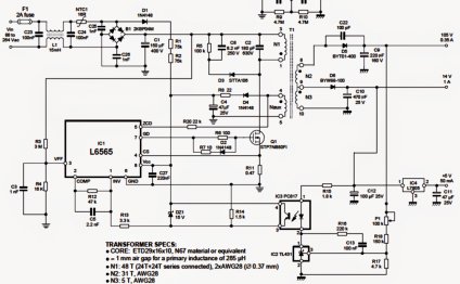
LED Light driver Circuit diagram
An LED is an unique type of diode made use of as an Optoelectronic product. Like a PN junction diode, it conducts when forward biased. But an unique function of the device is being able to give off sign when you look at the noticeable musical organization of this electromagnetic spectrum. A significant issue to push an LED would be to provide an almost continual present feedback. Frequently LED is driven making use of batteries or control devices like microcontrollers. Nevertheless these have actually their very own drawbacks, for example-low electric battery life etc. A feasible method would-be driving the LED making use of AC to DC power. Though AC to DC power making use of transformer is quite well-known and trusted, for applications like driving lots like LED, it shows is quite costly and more over it's not feasible to make a minimal existing sign utilizing transformer.
Keeping in mind most of the aspects, right here we design a straightforward circuit operating some LED from 230V AC. This really is achieved utilizing a capacitor based power supply. This is a low cost and efficient circuit and certainly will be utilized at domiciles.
Related Post:
230v LED Driver Circuit Principle:
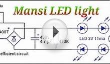
The basic principle behind this circuit is transformer less power. The key element is the X-rated AC capacitor that may lower the AC current to an appropriate quantity. These capacitors tend to be linked range to line and designed for high-voltage AC circuits. This decreased AC current will be rectified, blocked and managed to make a reduced voltage signal to drive two LEDs in show.
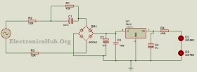
230v LED Driver Circuit Diagram:
230V LED Circuit Design:
Here the primary intention is to drive a series combination of LEDs by passing a present of about 20mA through all of them. Initial aspect of design the circuit is a voltage regulator. This could be offered utilizing a Zener diode, but since Zener diode can get heated up effortlessly, we favor using a voltage regulator IC that could supply accurate results. Right here we make use of LM78L12 voltage regulator IC delivering output current of about 12V at optimum 100mA present.
The minimum feedback current the IC to keep range legislation is just about 18V. maintaining this in mind as well as the DC rectified current of approximately 20V, we get the minimal unfavorable top of ripple voltage to be around 2V. The ripple voltage is double the minimum peak and is around 4V. The value of filter capacitor are computed keeping in mind the ripple voltage, ripple frequency, quiescent existing drawn by the regulator as well as the optimum load present. This is set up mathematically as:
C = (Iq+Io)/(F * Vr)
For Lm78L12, Iq is around 6mA, the necessary production present, Io is about 20mA, ripple frequency is double the line regularity of 50Hz and Vr is about 4V. replacing the values, we get capacitor is around 65uF. But keeping in account the reality of practical aspects, we chose a 47uF, 25V capacitor.
Since a connection rectifier is better entirely revolution rectification with additional performance, right here we make use of a connection rectifier with four diodes. The diodes tend to be selected bearing in mind the PIV rating of 100V. Here we utilize 1N4007.
For a voltage of 230V and result present of 20mA, the required impedance is all about 11.5k ohms. For a frequency of 50 Hz, the worthiness of capacitance is seen to be around 0.13uF. Nonetheless such a value is very low and we alternatively opted a value of 0.47uF producing result present around 33mA. (Based on calculations, a 1uF capacitor can produce existing around 72 mA.
Just how to Operate LED Driver Circuit?
The resistors R1 and R2 reduce inrush present through the AC mains supply. This AC voltage is more paid down because of the AC capacitor C1 which drops the current by around 210V. This decreased AC voltage is then rectified by the connection rectifier to obtain a rectified DC current of about 20V. This DC voltage is then blocked by the filter capacitor enabling the AC ripple indicators to pass through it therefore the DC sign is thus fed to your regulator IC. This filtered and rectified DC signal is then regulated because of the IC voltage regulator. The voltage-regulator utilized here ensures a maximum production existing of 100mA, which is further paid down to 20mA utilizing the resistor. Hence a regulated output of approximately 12V, 20mA is used to operate a vehicle two red LEDs.
The resistor R1 acts as a bleeder resistor permitting the capacitor C1 to discharge when the energy is switched off. This allows a lot of security.
Applications of 230V Light-emitting Diode Driver Circuit:
- This circuit can be used for home lightening systems.
- It can be used as an indicator circuit.
- One could fix this circuit utilizing the door bell to provide indication.
Limitations of LED Driver Circuit:
- Since 230V AC offer is being directly made use of right here, this circuit are dangerous.
- This circuit is most effective for domestic programs using single phase offer. Simply because in case of three-phase offer, if any of the phases accidently touches the feedback terminal, it can end up being quite dangerous.
RELATED VIDEO
Share this Post
Related posts

LED Light Reading
Absolutely. There is absolutely no reason you cannot make use of LED lights for reading or perhaps in various other general…
Read More
New LED Lighting products
These lamps, light sources, and luminaires round out of the latest products to incorporate Light-emitting Diode technology…
Read Morelatest posts
-
 LED Projector Lamp price January 16, 2024
 -
 LED light bulbs for sale cheap January 11, 2024
 -
 Light Bulb Shapes January 6, 2024
 -
 LED curing light for Gel nails January 1, 2024
 -
 LED Spot light bulbs December 27, 2023
 -
 Info on LED lights December 22, 2023
 -
 LED light Nail Dryer December 17, 2023
 -
 LED light for Gel polish December 12, 2023
 -
 LED Decorative Lamps December 7, 2023